")
")
Dynamic load plate


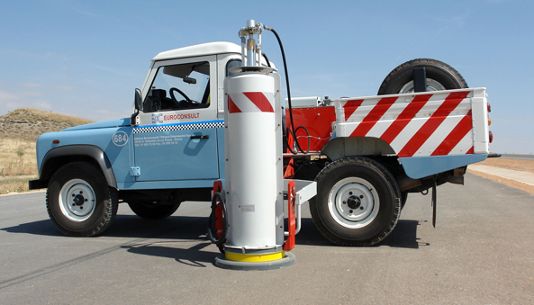
Measuring the strain modulus and bearing capacity of embankments and platforms
The dynamic load plate measures the strain modulus and bearing capacity of embankments and platforms both in granular form and when they are treated with cement or cement washed. It can be seen as similar to a static load plate as regards the parameters measured and the results obtained, but it also offers a number of advantages that make it a high-performance unit, i.e.:
- Set-up on site is fast and easy.
- High speed data acquisition.
- It can be moved around worksites and roads.
- Operations can be carried out very quickly.
- The readings can be used immediately on-site.
- The dynamic load plate comprises four basic elements:
- The impact generator.
- The plate measuring assembly and the associated electronic chain.
- The electronic control system for data acquisition and processing.
- The vehicle-mounted electrical cabinet and hydraulic power unit
Operation
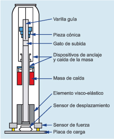
A dynamic load is applied by a weight that falls freely onto a visco-elastic component joined to the load plate. The hydraulic jack used to move the device also is centred on the load plate to act as a guide column for the weight as it falls.
The system comprises a polyurethane elastomer shock-absorbing spring with a Shore hardness of A 80 and an equivalent stiffness of 3 x 10⁶ N/m, which quickly damps the successive bounces.
The falling weight is a 125 kg cylindrical block, and the drop height is 0.5 m. This generates a force pulse comparable in its amplitude and duration to the passing of an axle load of 65 - 75 kN in 15 - 20 ms.
The electronic control, data acquisition and processing system is mounted in the vehicle cab. The conditioning circuits of the measuring plate force and movement sensors and the power circuits that control the impact generator are mounted on a rack.
The plate is connected to an industrial type laptop in the driver's cab which is equipped with a card for counting the pulses from the encoder that records the distance travelled. A keyboard enables the operator to input parameters to identify the site, monitor the readings from the impact generator and initiate the test cycle. A program developed specifically for this equipment automatically concatenates impacts and synchronises measurement data acquisition. The software generates and displays the stress/strain curve in real-time and calculates the dynamic modulus.
Measurements and calculations are displayed on screen, saved in the memory and can be printed so that results are available on the spot as soon as testing is completed.